 |
Segmented TurningDesign your first segmented project in 5 minutes with the Segmented Project Planner |
||
|
| Products | Classes | Free Plans | Hints | Buy Now | Gallery | Wood Costs | User Projects | FAQ |
7 Detailed Steps to Build Your Own Miter Sled
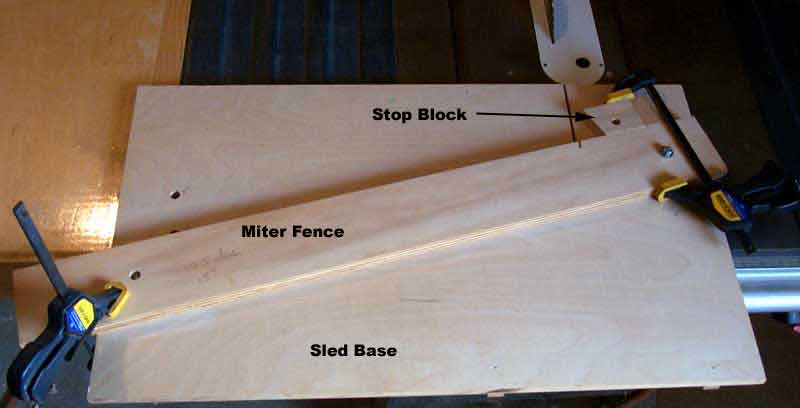
Thanks for taking a look at my plans for the AcuMiter™ Sled. If you build it carefully, you can expect to be able to make repeatable miter cuts that are accurate to well within .029°. For a 12 sided ring, that's an accuracy better than .1%. Here's a shot of my Miter Sled with fences for 5°, 10°, and 15°.
You should be able to construct the Sled Base and your initial Miter Fence for less than $20. Each additional Miter Fence adds only $2-$3.
Now, please print this document so you can take it to the shop with you. It would also be a good idea to write down or otherwise preserve the URL of this document so you can retrieve it again at a later date.
A Short Trigonometry Lesson: A little review of something you may have been through a long time ago, in high school, is the best place to start. Setting up the Miter Sled is all based on a simple right triangle like that pictured just below. This sample is set up for a Miter Angle of 10° and leg C is 29" (it just so happens that this agrees with the suggested width of your Miter Sled). In a right triangle the ratio of the long leg, C in this case, to the hypotenuse, R in this case, is the Cosine of the included angle, 10°, or Cos(10) = C/R. I get the value of R by knowing C and looking up in a table that Cos(10) = .984807753. In a like manner the Sine of the included angle is the ratio of the short leg, S in this case, to R or Sin(10) = S/R. So, having already determined the value of R via an awful long division problem, I can get S through a simple multiplication. I've included a table below that includes the relevant Sin and Cos values for segmented rings with 6 to 48 sides. This table also includes values for S when C is 29". If your table saw situation permits a Sled Base width of 29", you can just take the relevant S value from the table and start measuring. If not, you'll have to do the division to determine R and then the multiplication to get S for your situation. That's enough trigonometry!
Material Selection: Since you want to fabricate a Miter Sled that can give you extreme accuracy, the right materials must be used to ensure that it will do so in the future and under all conditions you can imagine. So the materials need to be stable with respect to moisture and temperature. For this reason, 3/4" Baltic Birch plywood is my choice for both the Sled Base and the Miter Fence. As a high quality plywood you can expect it to expand and contract equally in both the horizontal and vertical directions so the Miter Angle will not change with environmental changes. At 3/4" thick you can expect it's edges to stay straight and not warp. It also has a nice, smooth surface so there won't be anything to get snagged on.
Critical measurements: There are just 4 areas where measurements and squareness are critical to the success of your miter sled. In the drawing below these are R*Cos(Angle), R*Sin(Angle)+2, the squareness of the Sled Base, and the fit of the runners in your table saw slots. You can err on any of the first three and still get accurate cuts; it will just take longer to set up a Miter Fence for each new angle situation. But if you end up with runners that allow the Miter Sled to wobble, you'll never achieve repeatable, accurate cuts.
- R*Cos(Angle), 29" in the drawing, is one base of the triangle formed by your choice of Miter Angle and the width of the Sled Base. You can make your sled using a smaller width if your table saw is narrow enough to allow you to clamp the left end of the Miter Fence, but I don't recommend it because that will reduce the accuracy and repeatability of your resulting cuts. Whatever size you choose, make sure you know exactly its dimension and make the Sled Base as wide as practical for your situation.
- R*Sin(Angle)+2 is the second critical measurement. R*Sin(Angle) is the second leg of the triangle while the 2" is the distance down the right side of the Sled Base where the Miter Fence crosses it.
- You can play with Sin and Cos all day long and get poor accuracy if the Sled Base is not square. The bottom edge of the Sled Base must also exactly line up with the front edge of the table saw.
- The Runners on the bottom side of the Sled Base need to be very close to the dimensions of the slots in the top of your table saw. Not so tight as that they bind but not wobbly either. Also, you must make sure that the Sled Base is square to the runners. I'll show how you can do this very easily. With good fitting runners you'll get cuts that are repeatable time, after time, after time.
The Plan: Below is the layout of your Miter Sled, and following that, how to put it together. I'll describe the construction in terms of my situation using a Craftsman 10" saw. I'll make sure to include enough information so you can make the necessary changes to fit your situation if you cannot accommodate a Sled Base that is 29" wide.
Before you start construction: Raise your table saw blade as high as it will go and make sure it is perpendicular to the table. Also, be sure and do this every time you start a miter cutting session.
Step 1: Determine the size of your Miter Sled and its components As I said above, my table saw is a Craftsman 10" model and I'll describe how to size your Miter Sled based on its dimensions. The table top is 44" wide by 27" deep. The critical dimension, however, is distance from the left edge of the table to the right edge of the right-hand slot. For this saw that is 26". The Sled Base needs to have enough overhang on the left side of the table top do be able to clamp the Miter Fence while setting the Miter Angle. And you need a little space to the right of the right-hand table slot. So 29" wide works for my situation while giving me enough room to set up for segments as wide as 3-4 inches. As I said earlier, this dimension needs to be as accurate as possible; take your time.
The depth of the Sled Base depends on what Miter Angles you want to accommodate; the larger the angle, the deeper the Sled Base. I've sized this one to accommodate a Miter Angle of 30°, which means the Sled Base needs to be about 21" tall (R*Sin(30°)= 16.74..." + 2" across the top + 3" for the Miter Fence). I recommend that you make your Sled Base no shorter than 18" to minimize possible wobble/racking in the table slots. The Miter Fence will be something like 35" (29"/Cos(30°)= 33.48..." + overhang on the left side of the Sled Base). Using the same Sled Base, the Miter Fence for 5° miters would be about 31" long. You can always cut off what is not needed after the Miter Fence is set. The table below gives all the numbers you need to build a Miter Sled and Miter Fences for Miter Angles between 3.75° (48 sided rings) and 30° (6 sided rings).
| Miter Sled Layout Information | |||||||
| 6 | 30 | 0.866025404 | 0.5 | 29 | 33.48631561 | 16.74315781 | 16.75 |
| 8 | 22.5 | 0.923879533 | 0.382683432 | 29 | 31.38937381 | 12.01219331 | 12.015625 |
| 10 | 18 | 0.951056516 | 0.309016994 | 29 | 30.4924045 | 9.422671191 | 9.421875 |
| 12 | 15 | 0.965925826 | 0.258819045 | 29 | 30.02300923 | 7.770526581 | 7.765625 |
| 14 | 12.85714286 | 0.974927912 | 0.222520934 | 29 | 29.74578903 | 6.619060757 | 6.625 |
| 16 | 11.25 | 0.98078528 | 0.195090322 | 29 | 29.56814359 | 5.768458654 | 5.765625 |
| 18 | 10 | 0.984807753 | 0.173648178 | 29 | 29.44737174 | 5.113482441 | 5.109375 |
| 20 | 9 | 0.987688341 | 0.156434465 | 29 | 29.36148865 | 4.593148769 | 4.59375 |
| 22 | 8.181818182 | 0.989821442 | 0.142314838 | 29 | 29.29821357 | 4.169570526 | 4.171875 |
| 24 | 7.5 | 0.991444861 | 0.130526192 | 29 | 29.25023986 | 3.81792243 | 3.8125 |
| 26 | 6.923076923 | 0.992708874 | 0.12053668 | 29 | 29.21299563 | 3.521237513 | 3.515625 |
| 28 | 6.428571429 | 0.99371221 | 0.111964476 | 29 | 29.18349972 | 3.267515257 | 3.265625 |
| 30 | 6 | 0.994521895 | 0.104528463 | 29 | 29.15974011 | 3.048022823 | 3.046875 |
| 32 | 5.625 | 0.995184727 | 0.09801714 | 29 | 29.1403186 | 2.856250697 | 2.859375 |
| 34 | 5.294117647 | 0.995734176 | 0.092268359 | 29 | 29.12423887 | 2.687245741 | 2.6875 |
| 36 | 5 | 0.996194698 | 0.087155743 | 29 | 29.11077529 | 2.537171242 | 2.53125 |
| 38 | 4.736842105 | 0.996584493 | 0.082579345 | 29 | 29.09938917 | 2.403008511 | 2.40625 |
| 40 | 4.5 | 0.996917334 | 0.078459096 | 29 | 29.08967376 | 2.282349498 | 2.28125 |
| 42 | 4.285714286 | 0.997203797 | 0.074730094 | 29 | 29.08131726 | 2.173249561 | 2.171875 |
| 44 | 4.090909091 | 0.997452115 | 0.071339183 | 29 | 29.07407742 | 2.074120935 | 2.078125 |
| 46 | 3.913043478 | 0.997668769 | 0.068242413 | 29 | 29.06776367 | 1.983654344 | 1.984375 |
| 48 | 3.75 | 0.997858923 | 0.065403129 | 29 | 29.06222445 | 1.900760422 | 1.90625 |
Step 2: Cut the Major Pieces Using the measurements you've just decided upon, cut the Sled Base and the Miter Fence. Take your time and do the best you can to make the Sled Base square and the faces of the Miter Fence straight. The better you do, the more accurate your results will be.
Step 3: Setup the Layout Place the Sled Base on the Table Saw top with its long edge at the front edge of the saw table and position it left/right as necessary to get enough overhang on the left side to be able to clamp the Miter Fence and at least an inch or more room to the right of the right-hand table slot. Mark the position of the walls of the right-hand table slot on the Sled Base so that you can transfer the marks to both the top and bottom of the Sled Base . Then transfer these marks to the top and bottom of the Sled Base and draw connecting lines so you can see exactly where the right-hand runner will be. Put the Sled Base back in place on the table top and place the Miter Fence on top of the Sled Base in its approximate position to verify that everything will turn out ok. When you've got it right, mark the position of the pivot hole over the right-hand slot on the Sled Base. It should end up between 4 and 5 inches in from the back edge of the Sled Base. Go ahead and drill the 3/8" hole for the pivot bolt. Put the pivot bolt in the hole with the threads protruding through the top side of the Sled Base.
Step 4: Cutting the Runners Cut two runners to fit the two slots in your table saw top. In my case the slots are 3/4" wide by 3/8" deep so mine are just a little bit narrower and just a little bit shorter so that they slide easily down the full length of the slots without binding but also cannot be appreciably wiggled from side to side in the slots. For my table they are 21" long. The runner for the right side needs to be cut into two pieces to allow room for the head of the 3/8" bolt that will be used as the pivot point for the Miter Fence. Just measure them from the Sled Base.
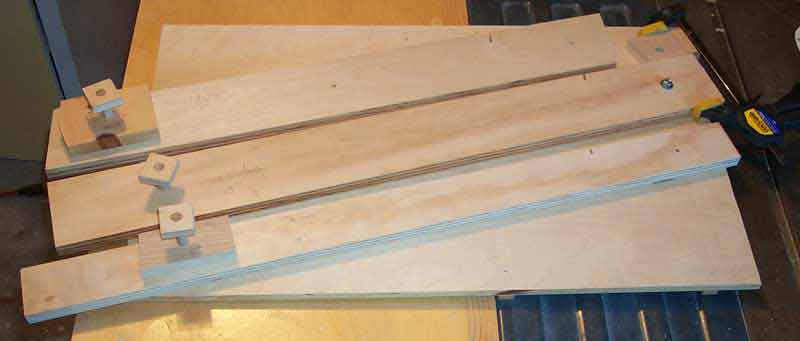
Step 5: Gluing the Runners First figure out how you can clamp a stop block across the front edge of your saw's table top. Don't attach it yet because you won't be able to see your runner marks on the front edge of the Sled Base. It only needs to extend above the table top surface enough to provide something to push the Sled Base up against during the gluing and it should be as wide as the Sled Base. Now put the right-hand runner pieces in the right-hand slot with shimming under and on their left edges so that the runner pieces stand a little proud of the table top and are held firmly against the right side of the slot. Don't forget to leave the gap for the 3/8" bolt. Also shim under and on the right side of the left-hand runner so that the Sled Base sits perfectly level on the two runners. Make the front faces of the runners even with the front face of the table top. The picture shows the runners shimmed in place. I've used dimes under the runners and 4 slips of paper on the inner edges.

Now apply glue to the right-hand runner pieces only and place the Sled Base. Make sure your horizontal position is where you want it, attach your stop block across the front edge of the saw's table top, and push the Sled Base firmly up against the stop block . Apply several weights on top of the Sled Base and let it dry. After drying, remove the side shim from the right runner pieces, apply glue to the left-hand runner and lay down the Sled Base again. This time push it against the stop block and to the right to make sure the right runner is up against the right side of its table slot, add weights, and let dry. After it dries, check out the movement of the Sled Base. It should slide relatively freely and there should be no wobble/racking motion possible. If that is the case, spray a little Silicon lubricant on the bottom of the Sled Base, tap some brads into the runners for insurance, and the Sled Base is complete.
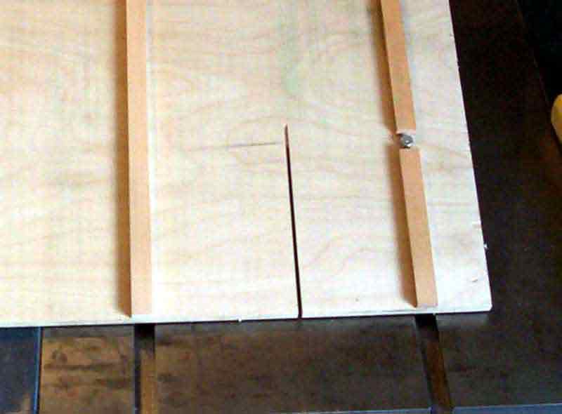
If you have wobble, you can apply a thin spacing material to the outside of the left runner such as a strip of paper or a thin layer of Crazy Glue or polyurethane. If it's too tight you can gently sand that same outside edge of the left runner. If you can't get it right, remove the left runner, clean up the joint, and try again making sure that the left runner is held firmly against the left edge of the left slot and the right runner is held firmly against the right edge of right slot. Here's what the runners look like after being glued in place
Step 6: Setting the Miter Fence Now comes the really critical part. For my case of setting the Miter Fence for 15° on a Sled Base that is 29" wide, I need to pivot the Miter Fence down until it crosses the left edge of the Sled Base at 7.770526581" lower than where it crosses the right edge of the Sled Base. If the Miter Fence crosses the right edge of the Sled Base at 2" then that point is at 9.770526581" or 9-49/64" down the left edge. So, attach the Miter Fence to the Sled Base and then use one of these two methods to get the initial Miter Fence setting on this 15° angle:
- Cut a straight strip of material long enough to span the Sled Base. Then place it across the top edge of the Sled Base with the Miter Fence in its approximate position so you won't have to be constantly subtracting the bias across the top edge. Then alternately measure off the 7-49/64" down the left edge below the cross peace and reset the cross peace until there's no more reason to move anything. Now clamp the left end of the Miter Fence down against the Sled Base so that the clamp will clear the left edge of the table saw top. This is how I set up my first Miter Sled.
- Accurately measure off a right angle and mark off on the two legs, the required 29" and 7-49/64" on a good sized piece of paper. Then trim off unneeded parts of the sheet so you can slip it under the Miter Fence and line up the short leg along the left side of the Sled Base. Then simply move the Miter Fence, and jockey the sheet up/down until you get the short leg on the left edge of the Sled Base with the Miter Fence crossing the short leg at the proper position and crossing the long leg at the proper position on the other end. Then clamp the left end of the Miter Fence down against the Sled Base. This is how I set up my last Miter Fence.
One way or another, get the Miter Fence set and clamp it down against the Sled Base so that the clamp clears the saw table top on the left side.
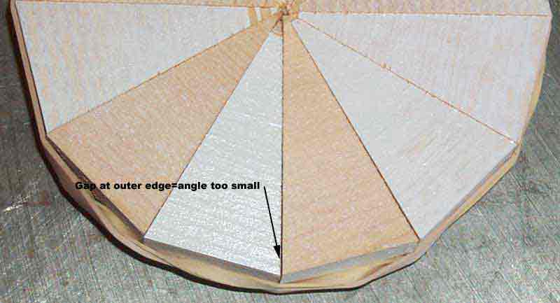
Step 6: Tuning the Miter Fence Position Now we need to cut a full segmented ring to make sure our setting is correct. Choose a straight piece of material, anything that will cut to a clean edge will suffice, that is at least 3" wide. Start by cutting off a piece 3"-4" long to use as a stop block. Then place and clamp the stop block so that you will be cutting segments that will almost make a disk rather than a ring because this is the most demanding accuracy situation. Now cut the appropriate number of segments (12 in this example), set them up in a ring and use a large rubber band to clamp it up. If everything is set right, there will be no gaps. If the angle setting is too large, there will be gaps at the inner edge of the ring. If the angle setting is too small, there will be gaps at the outer edge of the ring. If you get gaps that are uniform from the inner edge of the ring to the outer edge, either there is debris in some of the cuts or the saw blade is not vertical. Here is a 12 sided (15°) sample where the Miter Angle is set too shallow.
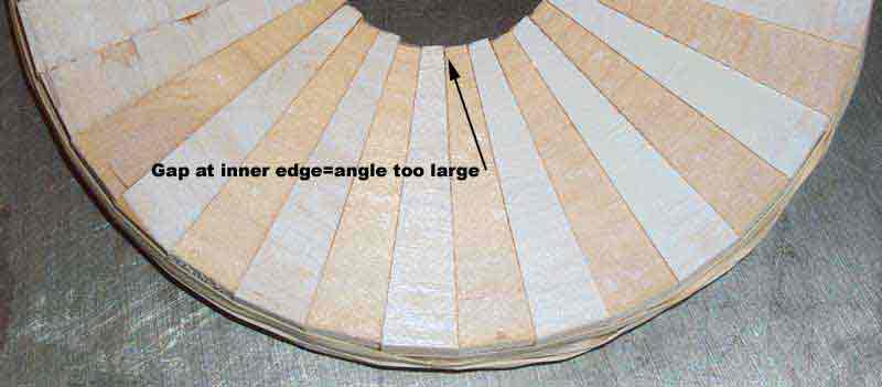
And here is a 36 sided (5°) example where the Miter Angle is just a bit too large. Actually, if you are going to make an error, this is the direction to do it because expansion of the wood at the inner end of the joint during gluing will take some of the slop out of it. For rings with only 1/2" or so wall thickness, this setting would be just fine. But it wouldn't cut the mustard for a full disk.
Since this first trial ring ought to be pretty close to perfect, you want to be sure you don't lose what degree of accuracy you have while adjusting. A simple way to do this is to clamp a block on Sled Base on the side of the Miter Fence away from the direction you need to move the Fence. Then loosen the clamp holding the Miter Fence in place and insert a slip of paper or two between the Miter Fence and the block and reclamp the Miter Fence. If you have to go back, the old setting is still there. Now you can cut another full ring worth of segments, assemble it, and decide what/if additional adjustment is needed.
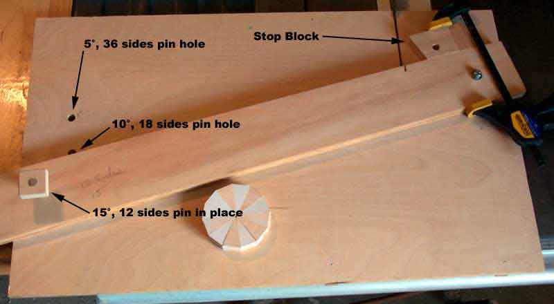
Step 7: Fixing the Miter Fence Position You now want to be able to remove and replace your new Miter Fence as necessary for various Miter Angles you want to cut, and you want to preserve the accurate placement you just achieved. To do this, simply drill a 1/2" hole through the stop block used to cut the segments, the Miter Fence, and the Sled Base out near the end of the Miter Fence. You place the hole near the left end of the Miter Fence to minimize error when the hole eventually gets augured out enough to allow the Miter Fence to wiggle. Then cutoff and place a 1/2" Oak dowel in the hole to pin the Miter Fence in place. When you dismount the Miter Fence to work another angle, just take out the pin and use it to attach the stop block to the Miter Fence so it won't get lost. Here's a picture of the final result in its operating configuration.
Page Last Updated: 5/31/2025